Solution: Ultrasonic testing – UT
Solution: Ultrasonic testing – UT

![]() Ultrasonic Testing - UT
Ultrasonic Testing - UT![]()
![]() In which region do you need this solution?
In which region do you need this solution?![]()
![]() Accreditation
Accreditation![]()
![]() Reflexionsschallverfahren und Durchschallungsverfahren
Reflexionsschallverfahren und Durchschallungsverfahren![]()
Reflection sound method (also pulse-echo method).
The smallest discontinuity that can be represented is greater than half the wavelength of the sound, which depends on the speed of sound of the material and the frequency of the probe. At a frequency of 4 MHz, this comes to about 0.7 mm in steel. The frequency cannot be increased indefinitely because the grain boundaries of the microstructure cause scattering and absorption, which reduces the penetration depth. The coarser the crystal formation in cast steel, for example, the longer wavelengths must be selected for the sound frequency. In the case of cast iron and austenite, testability is generally very limited. The largest material distances that are usually sonicated in the pulse echo method are 5 m, which corresponds to a sonic path of 10 m.
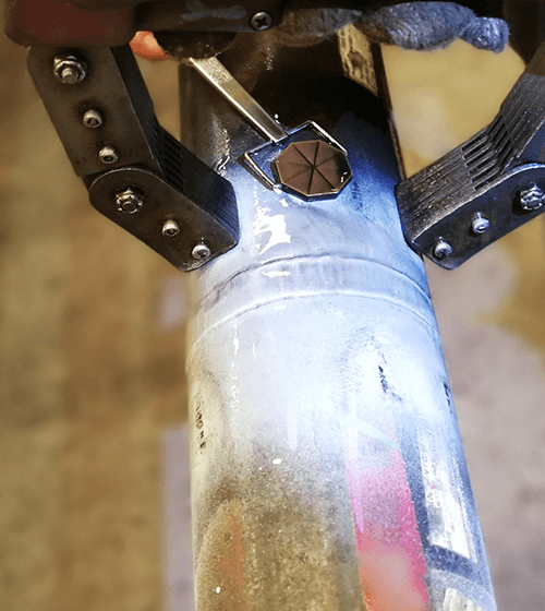
Ultrasonic testing UT
Ultrasonic testing is an acoustic method for finding material defects using ultrasound. It is one of the non-destructive testing methods. This allows components to be inspected even when installed.
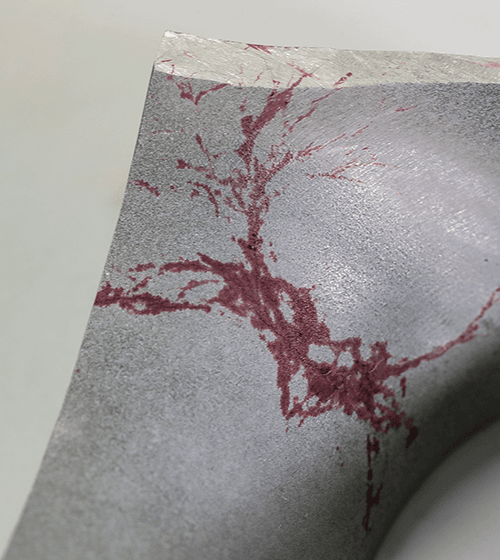
Application area
Ultrasonic testing is a suitable testing method for materials capable of conducting sound (including most metals) for the detection of internal and external defects, e.g. in weld seams, forgings, castings, semi-finished products or pipes. The detection of external (surface) defects is particularly important for parts where the other, usually internal, surface is not accessible.
UT Ultrasonic testing procedure
Two basic methods are used:
Reflection sound method (also pulse-echo method).
The smallest discontinuity that can be represented is greater than half the wavelength of the sound, which depends on the speed of sound of the material and the frequency of the probe. At a frequency of 4 MHz, this comes to about 0.7 mm in steel. The frequency cannot be increased indefinitely because the grain boundaries of the microstructure cause scattering and absorption, which reduces the penetration depth. The coarser the crystal formation in cast steel, for example, the longer wavelengths must be selected for the sound frequency. In the case of cast iron and austenite, testability is generally very limited. The largest material distances that are usually sonicated in the pulse echo method are 5 m, which corresponds to a sonic path of 10 m.
Impact echo method
This method involves two probes connected to the same ultrasonic unit. One probe transmits the pulse and the other receives the pulse on the exact opposite side of the specimen. This method is very special and is mostly used for testing for doubling. In addition, very near-surface zones can be tested, as this is not possible with the reflection sound method due to a “dead zone”. The “dead zone” occurs because a probe cannot transmit and receive at the same time.
Ultrasonic testing method
In ultrasonic testing, a coupling agent (e.g. paste, gel, water or oil) is applied to the surface of the workpiece. By means of a probe, which emits and receives ultrasound from 0.02 to 50 MHz, the surface to be inspected is scanned. This can be done manually, mechanized or automatically (within the production lines). In the latter case, the test piece is often immersed in a suitable liquid (immersion technique) or wetted in a defined manner in order to transmit the sound signal.
Changes in the acoustic properties at interfaces (e.g. a blowhole (cavity), inclusion, crack or other separation in the microstructure) inside the part under test reflect the acoustic pulse and send it back to the transducer in the probe, which acts as both transmitter and receiver. The elapsed time between transmission and reception allows the displacement to be calculated (pulse-echo method).
Based on the measured time difference, a signal image is generated and visualized on a monitor. Based on this image, the position can be determined and the size of the discontinuity can be estimated by comparing it with a substitute reflector (flat-bottom bore (circular-disk reflector), groove, transverse bore).